Industrial sensors are the eyes and ears of an automation system. They detect objects, measure temperature, pressure, level, flow, position and other process conditions, and send this information to a PLC (Programmable Logic Controller) for monitoring and control.
For students, technicians and automation engineers, understanding industrial sensor interfacing with PLC is one of the most important practical skills in industrial automation.
Whether you are working on a conveyor system, packaging machine, bottling plant, process plant or manufacturing line, proper sensor selection, wiring and PLC programming are essential for reliable machine operation.
What is Industrial Sensor Interfacing with PLC?
Industrial sensor interfacing means connecting a field sensor to the appropriate PLC input so that the PLC can receive and process the sensor signal.
A typical automation system works like this:
Sensor → PLC Input → PLC Program → PLC Output → Actuator
For example:
Proximity Sensor → PLC DI → PLC Logic → Motor Contactor/VFD
When a sensor detects a component, it changes its electrical output. The PLC receives this signal and executes the programmed logic.
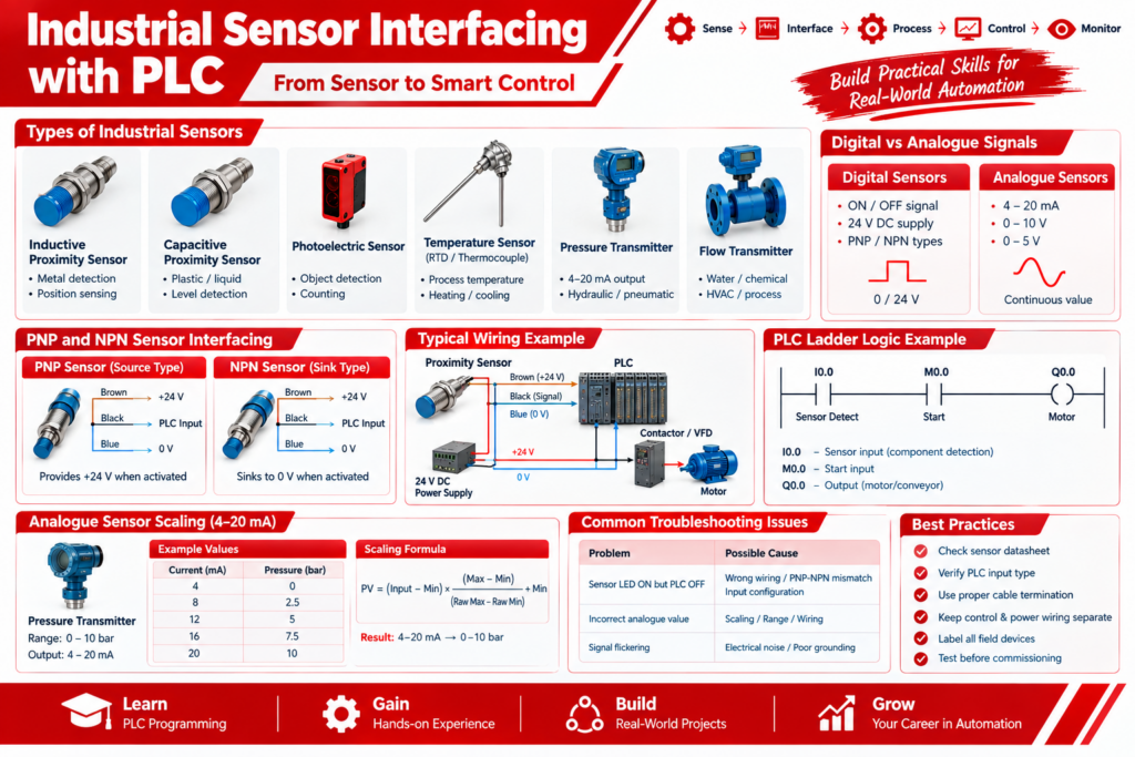
Digital sensors generally provide ON/OFF signals, while analogue sensors provide continuously varying signals such as 4–20 mA or 0–10 V.
Types of Industrial Sensors Used with PLC
Different industrial applications require different types of sensors.
1. Inductive Proximity Sensor
Inductive proximity sensors are commonly used for detecting metal objects.
Typical applications include:
- Conveyor object detection
- Machine position sensing
- Metal part detection
- Cylinder position feedback
- Counting applications
- Machine safety interlocks
The sensor produces a digital signal when a metallic target enters its sensing range.
2. Capacitive Proximity Sensor
Capacitive sensors can detect materials such as:
- Plastic
- Glass
- Powder
- Liquid
- Wood
- Granules
They are useful for level and material detection applications.
3. Photoelectric Sensor
Photoelectric sensors use light to detect objects.
They are commonly used in:
- Bottle counting
- Packaging machines
- Conveyor systems
- Product detection
- Object positioning
4. Temperature Sensor
Temperature can be measured using:
- RTD/PT100
- Thermocouple
- Temperature transmitter
Depending on the device, the PLC may receive a resistance, millivolt or standardized analogue signal.
5. Pressure Sensor/Transmitter
Pressure transmitters commonly provide 4–20 mA or other analogue outputs.
Applications include:
- Hydraulic pressure monitoring
- Pneumatic systems
- Water treatment
- Process plants
- Compressor systems
6. Level Sensor
Level sensors are used for monitoring:
- Water tanks
- Chemical tanks
- Process vessels
- Storage tanks
7. Flow Sensor/Flow Transmitter
Flow sensors and transmitters are widely used in:
- Water treatment plants
- Bottling plants
- Chemical plants
- HVAC systems
- Process industries
Digital Sensor Interfacing with PLC
Digital sensors provide an ON/OFF signal to the PLC.
For example:
Sensor OFF → PLC Input OFF
Sensor ON → PLC Input ON
A common industrial arrangement uses a 24 V DC sensor supply and a PLC digital input.
One of the most important concepts is understanding PNP and NPN sensors.
PNP and NPN Sensor Interfacing
PNP Sensor
A PNP sensor generally sources positive voltage on its output when activated.
Typical three-wire arrangement:
- Brown → +24 V DC
- Blue → 0 V
- Black → PLC input
The exact wiring must always be checked against the sensor and PLC input-module documentation. Schneider Electric also notes that PNP and NPN outputs use different current paths and must be matched appropriately with the PLC input configuration.
NPN Sensor
An NPN sensor generally sinks the output toward 0 V when activated.
Typical arrangement:
- Brown → +24 V DC
- Blue → 0 V
- Black → PLC input
However, the PLC input common and sourcing/sinking configuration must be verified from the particular PLC hardware manual.
Important: Do not assume that every PLC manufacturer uses the same sourcing/sinking terminology. Always check the specific input module datasheet before wiring.
Practical Example: Proximity Sensor with PLC
Consider a conveyor system where a proximity sensor detects a metal component.
Sequence
- Conveyor starts.
- Metal component approaches the sensor.
- Sensor detects the component.
- Sensor output changes state.
- PLC digital input becomes ON.
- PLC program processes the signal.
- PLC activates an output.
- Conveyor, pneumatic cylinder, counter or other actuator responds.
For example:
I0.0 = Component Detection Sensor
Q0.0 = Conveyor Motor
PLC logic can be designed so that the conveyor operates only when the required conditions are satisfied.
PLC Programming for Sensor Inputs
After wiring the sensor, the next step is PLC programming.
A simple ladder logic concept can be:
Sensor Input → Logic Condition → Output
For example:
|----[ Sensor_Detect ]----------------( Conveyor_Run )----|A more practical machine sequence may include:
|----[ Start ]----[/ Stop ]----[ Sensor_OK ]----( Motor )----|Additional conditions can be added for:
- Emergency stop
- Overload
- Machine permissive
- Safety interlock
- Timer
- Counter
- Fault condition
This is where practical PLC programming knowledge becomes important.
For students and engineers searching for best plc programming pune & nahre, sensor interfacing should be included as a core practical topic rather than learning PLC programming only through software simulation.
Analogue Sensor Interfacing with PLC
Digital sensors provide ON/OFF information, but analogue sensors provide a continuously changing value.
Common analogue signals include:
- 4–20 mA
- 0–10 V
- 0–5 V
4–20 mA is widely used in industrial process applications because current signals are generally more resistant to noise over industrial cable runs.
For example, consider a pressure transmitter:
Sensor Range: 0–10 bar
Output: 4–20 mA
The PLC must convert the raw analogue input into an engineering value.
Conceptually:
4 mA → 0 bar
12 mA → 5 bar
20 mA → 10 bar
The PLC program then scales the analogue input into engineering units.
Analogue Scaling in PLC
A basic linear scaling concept can be represented as:
Engineering Value = (Input − Minimum Input) × (Engineering Range / Input Range) + Engineering Minimum
For an industrial PLC, the actual raw-count range depends on the particular analogue input module.
The important steps are:
- Identify the sensor output.
- Check the sensor measuring range.
- Configure the PLC analogue input correctly.
- Read the raw analogue value.
- Scale it into engineering units.
- Display the value on HMI/SCADA.
- Generate alarms if required.
Incorrect scaling can result in an apparently working system showing incorrect process values.
Example: Temperature Sensor Interfacing
Suppose a temperature transmitter has:
Range: 0–100°C
Output: 4–20 mA
The PLC receives the current signal and converts it into temperature.
For example:
| Sensor Output | Temperature |
|---|---|
| 4 mA | 0°C |
| 8 mA | 25°C |
| 12 mA | 50°C |
| 16 mA | 75°C |
| 20 mA | 100°C |
The PLC can then display the temperature on an HMI.
It can also control:
- Heater
- Cooling fan
- Solenoid valve
- Pump
- Alarm
- VFD
based on programmed temperature limits.
Sensor Interfacing with HMI and SCADA
Sensor data does not have to remain inside the PLC.
The PLC can communicate sensor values to an HMI or SCADA system.
A typical architecture is:
Sensor → PLC → HMI
or
Sensor → PLC → SCADA → Database
The HMI can display:
- Sensor ON/OFF status
- Temperature
- Pressure
- Flow
- Level
- Production count
- Sensor fault
- High/low alarms
This creates a practical monitoring system for industrial machines and process plants.
Common Sensor Interfacing Problems
During commissioning, several problems can occur.
1. Sensor LED is ON but PLC Input is OFF
Possible causes:
- Incorrect wiring
- Wrong PLC input common
- PNP/NPN mismatch
- Incorrect input configuration
- Broken cable
2. PLC Input Remains Permanently ON
Possible causes include:
- Incorrect wiring
- Wrong sensor type
- Leakage current
- Short circuit
- Incorrect input configuration
Leakage current and input compatibility should be checked against the specifications of the sensor and PLC module.
3. Analogue Value is Incorrect
Check:
- 4–20 mA vs 0–10 V configuration
- Sensor range
- PLC analogue input configuration
- Scaling logic
- Wiring
- Grounding/shielding
4. Sensor Signal is Flickering
Possible causes:
- Electrical noise
- Poor cable routing
- Improper grounding
- Loose terminals
- Sensor alignment
- Insufficient filtering
Sensor cables should be properly routed and separated from high-noise power wiring where appropriate.
Practical Sensor Troubleshooting Procedure
When a PLC does not receive a sensor signal, follow a systematic procedure.
Step 1: Check Power Supply
Measure the sensor supply voltage.
For many industrial DC sensors, this may be around 24 V DC, but always verify the sensor’s specified operating range.
Step 2: Check Sensor LED
Operate the sensor and observe its indication.
Step 3: Measure Sensor Output
Use a multimeter to check whether the output changes when the sensor is activated.
Step 4: Check PLC Input
Monitor the corresponding PLC input online.
Step 5: Check PLC Program
Verify that the correct input address is used in the ladder logic.
Step 6: Check HMI Tag
If the PLC input is working but the HMI does not show the correct status, check the HMI tag/address mapping.
Step 7: Test the Complete Sequence
Finally, test the sensor under actual machine operating conditions.
Sensor Interfacing Practical Project
A simple training project can combine multiple sensors.
Project: Automated Conveyor Sorting System
Components:
- PLC
- 24 V DC power supply
- Inductive proximity sensor
- Photoelectric sensor
- Conveyor motor
- VFD
- Push buttons
- HMI
- Pneumatic cylinder
- Solenoid valve
Working
- Start the conveyor.
- Detect the incoming object.
- Identify the required position.
- Stop or slow the conveyor when required.
- Activate the pneumatic cylinder.
- Count the object.
- Display production count on HMI.
- Generate an alarm if the sensor does not respond.
This type of project gives students practical exposure to PLC programming, industrial sensors, digital inputs, analogue inputs, HMI, VFD and automation troubleshooting.
Best Practices for Industrial Sensor Interfacing
Always follow these practices:
- Check the sensor datasheet before wiring.
- Verify PLC input voltage and current specifications.
- Confirm PNP/NPN compatibility.
- Use the correct analogue input type.
- Verify sensor measuring range.
- Use proper cable termination.
- Keep control and power wiring appropriately separated.
- Check grounding and shielding requirements.
- Label every field device and PLC terminal.
- Test the sensor before commissioning the complete machine.
- Document PLC addresses and I/O mapping.
- Add suitable diagnostics and alarms in the PLC program.
Learn Industrial Automation Through Practical Training
Learning PLC programming becomes much more useful when students and technicians work with actual sensors, PLC hardware, HMI systems, VFDs and industrial control panels.
A practical PLC training program should cover:
- PLC fundamentals
- Digital I/O
- PNP and NPN sensors
- Proximity sensors
- Photoelectric sensors
- Analogue 4–20 mA signals
- 0–10 V signals
- Temperature sensors
- Pressure sensors
- Level and flow sensors
- Timers and counters
- HMI programming
- VFD control
- Industrial communication
- Troubleshooting
- Machine automation projects
For anyone searching for best plc programming pune & nahre, practical sensor interfacing is an important skill to develop alongside ladder logic and PLC hardware programming.
Conclusion
Industrial sensor interfacing is a fundamental part of PLC-based automation. A successful automation system depends not only on writing PLC logic but also on selecting the correct sensor, understanding its output signal, wiring it correctly, configuring the PLC input and testing the complete signal path.
From a simple PNP proximity sensor to a 4–20 mA pressure transmitter, the same basic principle applies:
Sense → Interface → Process → Control → Monitor
With hands-on practice using real industrial sensors, PLCs, HMIs and automation panels, students and engineers can develop the troubleshooting skills required for real-world industrial automation projects.
Industrial Sensor Interfacing, PLC Sensor Wiring, PLC Programming, PNP Sensor, NPN Sensor, Proximity Sensor, 4–20 mA Sensor, Analogue Sensor, Digital Sensor, HMI, SCADA, Industrial Automation, PLC Training, best plc programming pune & nahre