Motor control is one of the most important topics in industrial automation and PLC programming. Industrial motors are used in conveyors, pumps, fans, compressors, mixers, blowers, packaging machines, and many other applications.
Understanding motor control and starter circuits helps students, technicians, electricians, and automation engineers learn how a PLC can control motors safely and efficiently.
For students and professionals searching for best plc programming pune & nahre, practical knowledge of DOL starters, star-delta starters, motor contactors, overload relays, interlocks, timers, and PLC ladder logic is very useful.
1. What is a Motor Starter?
A motor starter is an electrical arrangement used to start, stop, and protect an electric motor.
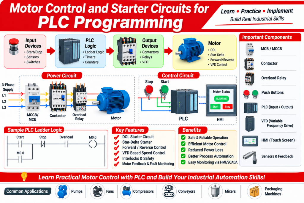
A typical motor starter circuit can include:
- MCCB or MCB
- Contactor
- Overload relay
- Start push button
- Stop push button
- Auxiliary contacts
- Control relay
- PLC digital inputs and outputs
- Motor protection devices
The power circuit supplies energy to the motor, while the control circuit determines when the motor should start or stop.
2. Why Motor Control is Important in PLC Programming
PLC programming is not only about writing ladder logic. A programmer should understand how the actual motor starter, contactor, overload relay, sensors, and feedback signals work.
A basic PLC motor-control application can include:
Start Push Button → PLC Input → PLC Logic → PLC Output → Contactor → Motor
The PLC can also monitor:
- Motor running feedback
- Overload trip
- Emergency stop status
- Motor fault
- Auto/manual selection
- Start permissive
- Stop command
This combination of electrical wiring and PLC logic makes motor control an important practical automation skill.
3. DOL Starter Circuit
DOL means Direct-On-Line starter.
It is one of the simplest methods of starting a three-phase induction motor. A contactor connects the motor directly to the supply through the required protection devices.
Main Components of a DOL Starter
- MCCB/MCB
- Contactor
- Overload relay
- Start push button
- Stop push button
- Auxiliary contact
- Motor
- PLC output, when PLC control is required
Basic PLC DOL Sequence
A simple PLC-controlled DOL motor can work as follows:
- Operator presses the Start button.
- PLC receives the Start input.
- PLC checks the required permissives.
- PLC energizes the contactor output.
- Motor starts.
- Auxiliary contact provides running feedback.
- Pressing Stop removes the motor command.
- An overload or fault condition can stop the motor.
The PLC should control the sequence while appropriate electrical protection and isolation remain part of the motor-control system.
4. Star-Delta Starter with PLC
A star-delta starter is commonly used for suitable three-phase induction motors where reduced-voltage starting is required.
The motor initially starts in the star connection and, after the required acceleration period, changes to the delta connection. A PLC can control this sequence using timers, contactor outputs, feedback, and interlocks.
Basic Star-Delta PLC Sequence
Start → Main Contactor ON → Star Contactor ON → Timer → Star OFF → Transition Delay → Delta ON
The PLC program should ensure that the star and delta contactors cannot be commanded simultaneously. Hardware electrical/mechanical interlocking should also be provided.
PLC Inputs
Typical inputs may include:
- Start push button
- Stop push button
- Overload feedback
- Main contactor feedback
- Star contactor feedback
- Delta contactor feedback
- Emergency stop status
- Auto/manual selector
PLC Outputs
Typical outputs may include:
- Main contactor
- Star contactor
- Delta contactor
- Motor running indication
- Fault indication
5. Forward and Reverse Motor Control
Some machines require the motor to rotate in both directions.
A forward/reverse starter generally uses two contactors:
- Forward contactor
- Reverse contactor
The control system must prevent both contactors from operating together.
PLC logic can include:
Forward Command → Forward Contactor
Reverse Command → Reverse Contactor
Electrical and mechanical interlocking should be used in addition to PLC logic. A suitable transition delay can also be required before changing direction, depending on the application.
6. Motor Control Using VFD
A Variable Frequency Drive (VFD) provides variable-speed motor control.
Instead of simply switching the motor ON and OFF, the PLC can send commands such as:
- Run
- Stop
- Forward
- Reverse
- Speed reference
- Reset fault
The PLC and VFD can communicate through digital signals, analog signals, or industrial communication networks such as Modbus, PROFINET, or EtherNet/IP, depending on the equipment.
Example VFD Application
A PLC may receive a pressure sensor signal and control a pump through a VFD.
Pressure Sensor → PLC → PID Control → Speed Reference → VFD → Pump
This type of application combines PLC programming, instrumentation, PID control, and motor control.
7. PLC Ladder Logic for Motor Start/Stop
A basic motor start/stop program generally uses:
- Start input
- Stop input
- Motor output
- Motor auxiliary feedback
- Overload signal
A holding or seal-in function allows the motor command to remain active after the Start push button is released.
For practical PLC training, this simple circuit is an excellent starting point before moving to star-delta, VFD, sequential motor control, and automatic process control.
8. Interlocks in Motor Control
Interlocks are extremely important in industrial motor-control applications.
Examples include:
Forward/Reverse Interlock
Forward and reverse outputs must not operate together.
Star/Delta Interlock
Star and delta contactors must not operate simultaneously.
Pump Interlock
A pump may only start when:
- Tank level is sufficient
- Valve is open
- No overload exists
- Emergency stop is healthy
- Required process permissives are available
Conveyor Interlock
A conveyor may only run when:
- Motor is healthy
- Safety conditions are satisfied
- Downstream equipment is ready
- No emergency-stop condition exists
Good PLC programming should clearly define these permissives and fault conditions.
9. Motor Feedback and Troubleshooting
A PLC output being ON does not necessarily prove that the motor is physically running.
For better diagnostics, the PLC can monitor:
- Contactor auxiliary feedback
- VFD running signal
- VFD fault signal
- Overload relay
- Motor protection relay
- Motor current
- Speed feedback
This allows the HMI or SCADA system to display useful messages such as:
Motor Start Command ON
Motor Running
Motor Overload
VFD Fault
Motor Start Failed
Feedback-based programming improves troubleshooting and makes industrial automation systems easier to maintain.
10. HMI Integration with Motor Control
An HMI can provide an operator interface for controlling and monitoring motors.
Typical HMI functions include:
- Motor Start
- Motor Stop
- Auto/Manual selection
- Motor status
- Running indication
- Fault indication
- Current display
- Speed display
- VFD frequency
- Alarm history
- Start/stop counters
For example:
HMI Start Command → PLC → Motor Starter/VFD
and
Motor/VFD Feedback → PLC → HMI
This creates a practical PLC-HMI motor-control system.
11. Practical PLC Motor Control Projects
Students can improve their PLC programming skills by building practical projects such as:
- DOL motor starter
- Star-delta starter
- Forward/reverse motor
- Two-motor sequence control
- Conveyor motor control
- Pump alternation system
- VFD speed control
- Automatic pump control using level sensor
- Motor control with HMI
- Motor fault monitoring with SCADA
These projects help connect electrical control circuits with real PLC programming.
12. Skills Required for Motor Control PLC Programming
To work effectively with industrial motor-control systems, learners should understand:
- Electrical control circuits
- Three-phase motors
- DOL starter
- Star-delta starter
- Contactors
- Overload relays
- MCCB/MCB
- Auxiliary contacts
- PLC digital inputs
- PLC digital outputs
- Ladder logic
- Timers
- Counters
- Interlocks
- HMI
- VFD
- Industrial communication
- Troubleshooting
- Electrical panel wiring
Learning these topics through practical projects can make PLC training much more useful than learning ladder logic alone.
13. Motor Control and Industrial Automation Training
Motor-control circuits are a foundation for many industrial automation applications. Once a learner understands DOL, star-delta, forward/reverse, VFD control, interlocks, and feedback, it becomes easier to develop larger PLC applications.
This is why practical motor-control exercises are commonly included in industrial automation and PLC training programs.
For anyone looking for best plc programming pune & nahre, learning through actual trainer panels, PLC hardware, contactors, motors, VFDs, sensors, and HMI systems can provide valuable hands-on experience.
Conclusion
Motor Control and Starter Circuits for PLC Programming are essential topics for anyone learning industrial automation.
Starting with a simple DOL circuit and gradually moving toward star-delta starters, forward/reverse control, VFD applications, HMI monitoring, interlocks, feedback, and automatic motor sequencing gives learners a strong practical foundation.
PLC programming becomes much easier to understand when the ladder logic is connected to real electrical control circuits and industrial equipment.
Keywords: PLC programming, motor control, motor starter, DOL starter, star delta starter, PLC ladder logic, VFD programming, motor control circuit, industrial automation, PLC motor control, HMI motor control, electrical panel wiring, best plc programming pune & nahre.